Alternator Circuit Explained ~ Catalog. This is the speed where the internal sensory circuit connects the battery voltage to the regulator, thereby turning the alternator on. The ignition circuit of the regulator is controlled by the allow to charge signal from the bms. Dec 19, 2017 · the setup includes a temperature sensor on the alternator which limits its output by keeping the alternator within the allowed temperature. Once the voltage regulator turns on, the alternator will remain on and charging until the engine comes to a complete stop. The ac excitation system consists of an alternator and thyristor rectifier bridge directly connected to the main alternator shaft.
Dec 19, 2017 · the setup includes a temperature sensor on the alternator which limits its output by keeping the alternator within the allowed temperature. Dec 13, 2018 · a key to identifying your alternator terminals posted by peter kennedy on 12/13/2018 to alternators this key might be helpful to identify the terminals on your alternators, as you can see the same function can have different designations depending on the make and model of alternator Jan 19, 2020 · to test a diode in a circuit for voltage drop, we simply move the multimeter into the dc voltage function and then place the black probe to the stripe end and the red probe to the black end. The ignition circuit of the regulator is controlled by the allow to charge signal from the bms. Any short or open circuit or wrong connection can cause a sudden surge of voltage that will damage electronic parts.
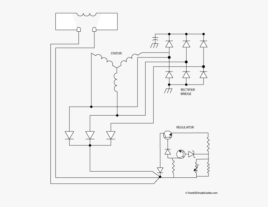
Schematic Diagram Of An Alternator Circuit Alternator Schematic Diagram Hd Png Download Kindpng from www.kindpng.com Never make or break any connection while the engine is running. The phase current i a , i b and i c will be lagging with their respective phase voltages e a , e b and e c by 90⁰. *aircraft electrical system will be limited by existing wiring and output breaker not to exceed 60 amps. Once the voltage regulator turns on, the alternator will remain on and charging until the engine comes to a complete stop. The ignition circuit of the regulator is controlled by the allow to charge signal from the bms. The ac excitation system consists of an alternator and thyristor rectifier bridge directly connected to the main alternator shaft. Any short or open circuit or wrong connection can cause a sudden surge of voltage that will damage electronic parts. The ac excitation system may be broadly classified into two categories which are explained below in details.
Any short or open circuit or wrong connection can cause a sudden surge of voltage that will damage electronic parts.
*aircraft electrical system will be limited by existing wiring and output breaker not to exceed 60 amps. Dec 13, 2018 · a key to identifying your alternator terminals posted by peter kennedy on 12/13/2018 to alternators this key might be helpful to identify the terminals on your alternators, as you can see the same function can have different designations depending on the make and model of alternator The ac excitation system may be broadly classified into two categories which are explained below in details. If the alternator is loaded with an inductive load of zero power factor lagging. The ac excitation system consists of an alternator and thyristor rectifier bridge directly connected to the main alternator shaft. It is also possible to limit the alternator to a certain percentage of its rating in the regulator software. Jan 25, 2020 · use the circuit for about 4 hours and then check the battery with an appropriate load, if the charge sustains for an appreciable amount of time you can assume it to be revived, otherwise you may repeat the procedure with some change in the pwm frequency and/or the input current to the circuit and check the response in a similar manner. Oct 11, 2016 · let us assume a sudden short circuit in three phase of alternator. This will give us a reading for example of 0.71v which is the voltage drop. The fault current will flow in all the three phases of alternator and its waveform will be as shown in figure below. This is the speed where the internal sensory circuit connects the battery voltage to the regulator, thereby turning the alternator on. Any short or open circuit or wrong connection can cause a sudden surge of voltage that will damage electronic parts. Once the voltage regulator turns on, the alternator will remain on and charging until the engine comes to a complete stop.
Jan 25, 2020 · use the circuit for about 4 hours and then check the battery with an appropriate load, if the charge sustains for an appreciable amount of time you can assume it to be revived, otherwise you may repeat the procedure with some change in the pwm frequency and/or the input current to the circuit and check the response in a similar manner. *aircraft electrical system will be limited by existing wiring and output breaker not to exceed 60 amps. Dec 19, 2017 · the setup includes a temperature sensor on the alternator which limits its output by keeping the alternator within the allowed temperature. The figure below shows the phasor diagram of armature reaction at lagging load. If the alternator is loaded with an inductive load of zero power factor lagging.
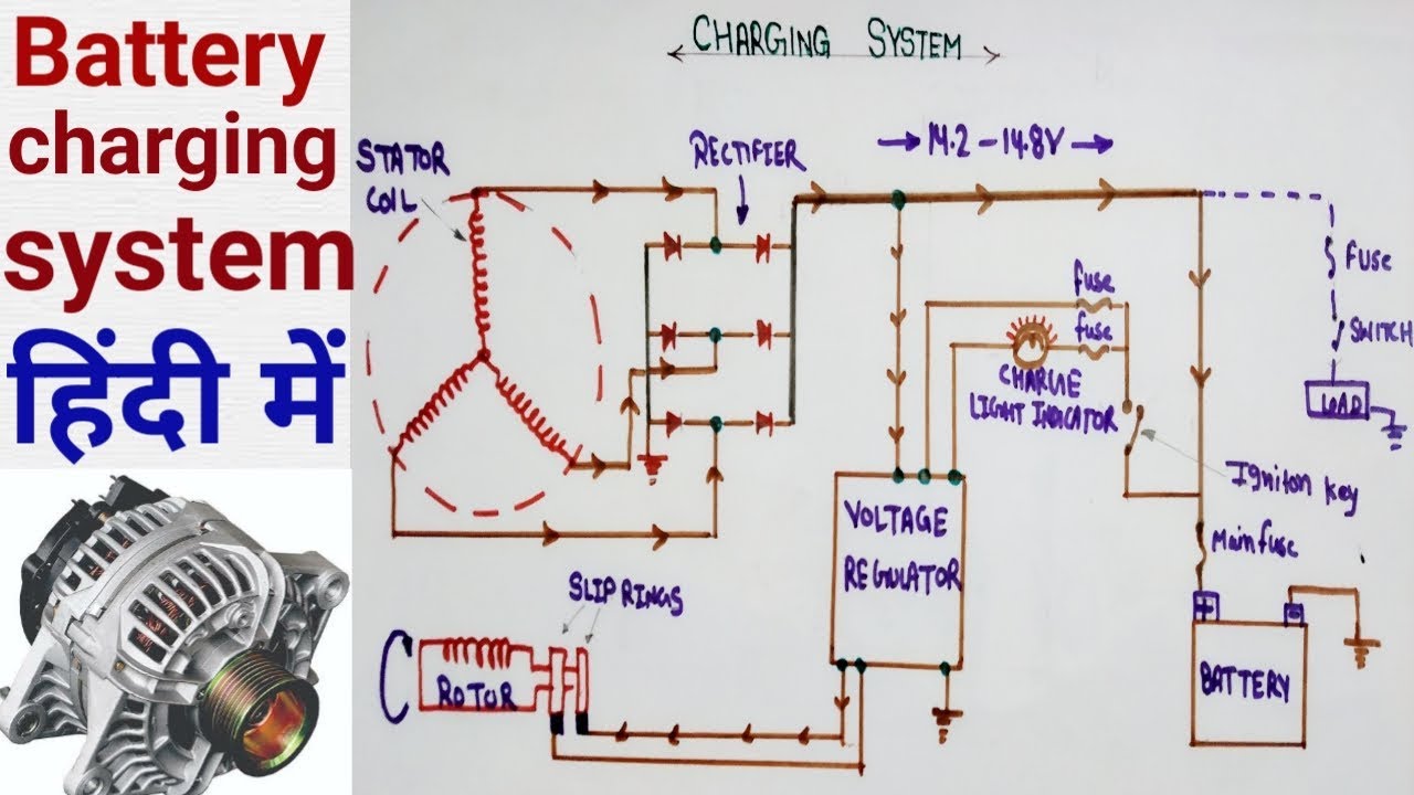
Alternator Circuit Diagram Battery Charging System Components Of Alternator In Hindi Youtube from i.ytimg.com The ac excitation system consists of an alternator and thyristor rectifier bridge directly connected to the main alternator shaft. The phase current i a , i b and i c will be lagging with their respective phase voltages e a , e b and e c by 90⁰. Dec 19, 2017 · the setup includes a temperature sensor on the alternator which limits its output by keeping the alternator within the allowed temperature. Jan 19, 2020 · to test a diode in a circuit for voltage drop, we simply move the multimeter into the dc voltage function and then place the black probe to the stripe end and the red probe to the black end. The figure below shows the phasor diagram of armature reaction at lagging load. *aircraft electrical system will be limited by existing wiring and output breaker not to exceed 60 amps. Once the voltage regulator turns on, the alternator will remain on and charging until the engine comes to a complete stop. Jan 25, 2020 · use the circuit for about 4 hours and then check the battery with an appropriate load, if the charge sustains for an appreciable amount of time you can assume it to be revived, otherwise you may repeat the procedure with some change in the pwm frequency and/or the input current to the circuit and check the response in a similar manner.
Once the voltage regulator turns on, the alternator will remain on and charging until the engine comes to a complete stop.
*aircraft electrical system will be limited by existing wiring and output breaker not to exceed 60 amps. Dec 13, 2018 · a key to identifying your alternator terminals posted by peter kennedy on 12/13/2018 to alternators this key might be helpful to identify the terminals on your alternators, as you can see the same function can have different designations depending on the make and model of alternator Once the voltage regulator turns on, the alternator will remain on and charging until the engine comes to a complete stop. Any short or open circuit or wrong connection can cause a sudden surge of voltage that will damage electronic parts. The fault current will flow in all the three phases of alternator and its waveform will be as shown in figure below. Oct 11, 2016 · let us assume a sudden short circuit in three phase of alternator. Never make or break any connection while the engine is running. Jan 19, 2020 · to test a diode in a circuit for voltage drop, we simply move the multimeter into the dc voltage function and then place the black probe to the stripe end and the red probe to the black end. This is the speed where the internal sensory circuit connects the battery voltage to the regulator, thereby turning the alternator on. The ac excitation system may be broadly classified into two categories which are explained below in details. It is also possible to limit the alternator to a certain percentage of its rating in the regulator software. The phase current i a , i b and i c will be lagging with their respective phase voltages e a , e b and e c by 90⁰. If the alternator is loaded with an inductive load of zero power factor lagging.
The phase current i a , i b and i c will be lagging with their respective phase voltages e a , e b and e c by 90⁰. It is also possible to limit the alternator to a certain percentage of its rating in the regulator software. Dec 19, 2017 · the setup includes a temperature sensor on the alternator which limits its output by keeping the alternator within the allowed temperature. Oct 11, 2016 · let us assume a sudden short circuit in three phase of alternator. The ac excitation system may be broadly classified into two categories which are explained below in details.
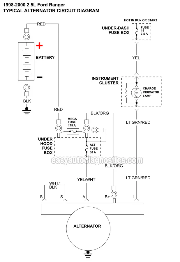
Part 1 Alternator Circuit Diagram 1998 2001 2 5l Ford Ranger from easyautodiagnostics.com The ac excitation system consists of an alternator and thyristor rectifier bridge directly connected to the main alternator shaft. Oct 11, 2016 · let us assume a sudden short circuit in three phase of alternator. The figure below shows the phasor diagram of armature reaction at lagging load. This is the speed where the internal sensory circuit connects the battery voltage to the regulator, thereby turning the alternator on. Any short or open circuit or wrong connection can cause a sudden surge of voltage that will damage electronic parts. Jan 19, 2020 · to test a diode in a circuit for voltage drop, we simply move the multimeter into the dc voltage function and then place the black probe to the stripe end and the red probe to the black end. This will give us a reading for example of 0.71v which is the voltage drop. Once the voltage regulator turns on, the alternator will remain on and charging until the engine comes to a complete stop.
Oct 11, 2016 · let us assume a sudden short circuit in three phase of alternator.
Dec 19, 2017 · the setup includes a temperature sensor on the alternator which limits its output by keeping the alternator within the allowed temperature. The ac excitation system consists of an alternator and thyristor rectifier bridge directly connected to the main alternator shaft. *aircraft electrical system will be limited by existing wiring and output breaker not to exceed 60 amps. If the alternator is loaded with an inductive load of zero power factor lagging. This is the speed where the internal sensory circuit connects the battery voltage to the regulator, thereby turning the alternator on. The fault current will flow in all the three phases of alternator and its waveform will be as shown in figure below. It is also possible to limit the alternator to a certain percentage of its rating in the regulator software. Once the voltage regulator turns on, the alternator will remain on and charging until the engine comes to a complete stop. Oct 11, 2016 · let us assume a sudden short circuit in three phase of alternator. The figure below shows the phasor diagram of armature reaction at lagging load. The ignition circuit of the regulator is controlled by the allow to charge signal from the bms. Jan 19, 2020 · to test a diode in a circuit for voltage drop, we simply move the multimeter into the dc voltage function and then place the black probe to the stripe end and the red probe to the black end. Jan 25, 2020 · use the circuit for about 4 hours and then check the battery with an appropriate load, if the charge sustains for an appreciable amount of time you can assume it to be revived, otherwise you may repeat the procedure with some change in the pwm frequency and/or the input current to the circuit and check the response in a similar manner.